U-he article
Source Link
user1079505
  • 17.8k
  • 2
  • 28
  • 69

(note Note, this is not a state of the art algorithm to solve numerical equations, but rather a simple way to present the idea. In particular, I made two approximations:

  • the present value of LFO output is approximated by the value from the previous time step
  • the LFO output is assumed to be constant between the time steps.

No such approximations were present in the analytical formula (Eq. 5). See e.g. Urs Heckmann article on Zero Delay Feedback about attempts to minimize the error introduced by the numerical algorithms.

Nevertheless, the value of LFO at a given time is calculated based on the value(s?) from the previous time steps, so in a way there is very deep recursion.

(note, this is not a state of the art algorithm to solve numerical equations, but rather a simple way to present the idea)

Note, this is not a state of the art algorithm to solve numerical equations, but rather a simple way to present the idea. In particular, I made two approximations:

  • the present value of LFO output is approximated by the value from the previous time step
  • the LFO output is assumed to be constant between the time steps.

No such approximations were present in the analytical formula (Eq. 5). See e.g. Urs Heckmann article on Zero Delay Feedback about attempts to minimize the error introduced by the numerical algorithms.

Nevertheless, the value of LFO at a given time is calculated based on the value(s?) from the previous time steps, so in a way there is very deep recursion.

moar maths
Source Link
user1079505
  • 17.8k
  • 2
  • 28
  • 69

If you modulate RATEMathematically, LFO can be described as a function of aninternal phase of the oscillator LFO = func(phi) where func represents the oscillator function, e.g. sine, square, triangle, sawtooth, etc.

The phase increases in time at a given rate: phi(t) = integral from 0 to t over 2π r(t)dt where r is the rate.

With LFO withmodulating its own rate, the outputrate can be expressed as:

r(t) = r0 + m·LFO(phi(t)) where r₀ is the base rate setting on the LFO, and m is the modulation depth, or more likely as: r(t) = r0 * exp(m·LFO(phi(t))) as to me exponential modulation seems more logical for this parameter. The whole equation for LFO then becomes: LFO=func(integral(r0·exp[m·LFO(phi(t))]dt) So indeed there is a self-reference of that LFO in the equation, it couldwhich might be expressedconfusing. Mathematicians don't solve this type of equations by calling the following schematicfunction over and over, but rather by smartly guessing a function (in this case: LFO(t)) which would solve the equation. If you want to learn more mathoverflow is probably a good site.

A digital synthesizer solves this equation numerically, with an algorithm that could be schematically presented as:

for each time step:
    phase += rate * dt
    lfo_output = lfo_functionfunc(phase % 360°)
    rate = rate_setting +* exp( modulation_depth * lfo_output )

where lfo_function represents the shape of the lfo (sinenote, trianglethis is not a state of the art algorithm to solve numerical equations, custom...but rather a simple way to present the idea).

I cannot provideWhile finding the functional representation of the LFO.output might be difficult, I guess it requires solvingcan provide some integral to take into accountintuition:

  1. the function will be periodic
  2. the lower parts of the LFO function will become wider and the upper ones thinner (or the other way round for negative modulation)
  3. for symmetric initial LFO shape and bipolar modulation, the effective rate will decrease, because stretching the lower parts by some factor, and squeezing the top parts by the same factor results in overall stretching of the waveform

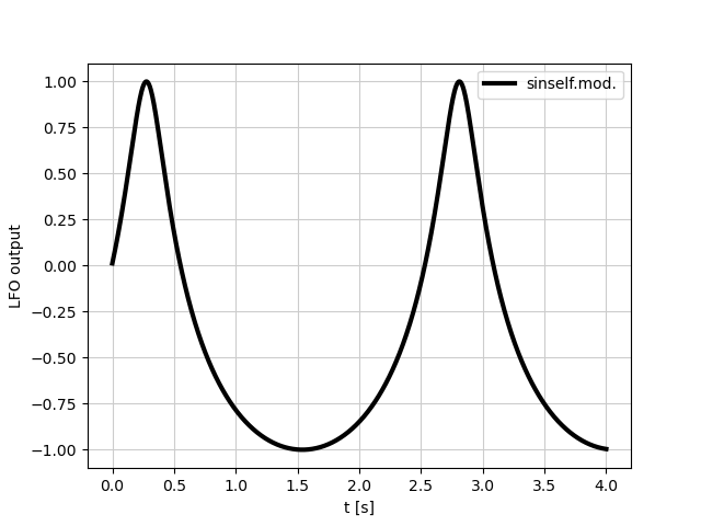
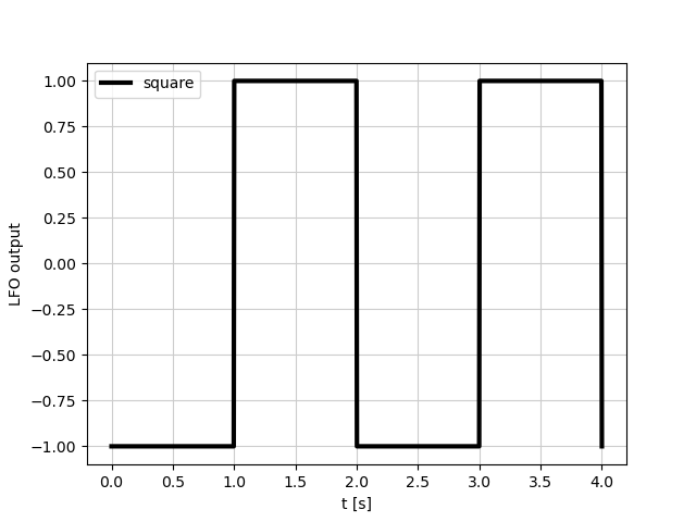
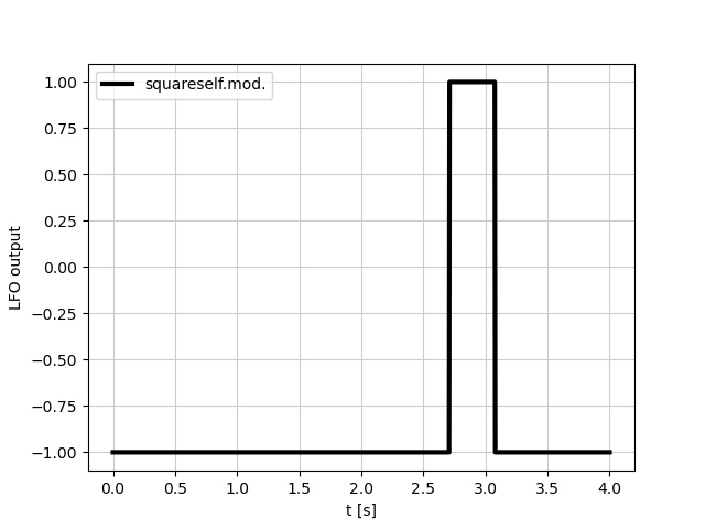
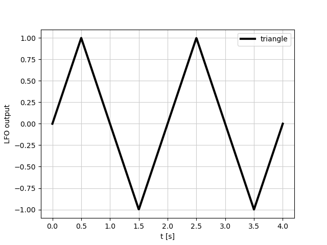
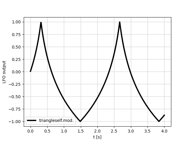
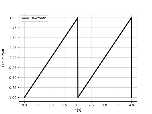
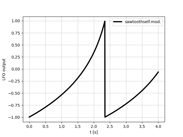
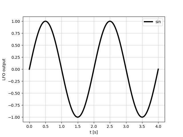
Below I present the shape of LFOeffect on several common oscillator shapes. In all cases, thebase rate settingr₀ = 0.5 Hz (period 2s) and modulation depth. I would expect the function to be always periodic m = 1, with the period depending on these three factorsexponential modulation (Eqs. This implies4 and 5). Notice how the upper and lower parts of the waveform are deformed differently, and how the effective rate you setchanges differently depending on the LFOwaveform shape (base rate without modulation) will not be the actual ratein particular compare square wave with the modulationothers). sine wave sine wave self modulated square wave square wave self modulated triangle wave triangle wave self modulated sawtooth wave sawtooth wave self modulated
If you modulate RATE of an LFO with the output of that LFO, it could be expressed by the following schematic algorithm:

for each time step:
    phase += rate * dt
    lfo_output = lfo_function(phase % 360°)
    rate = rate_setting + modulation_depth * lfo_output

where lfo_function represents the shape of the lfo (sine, triangle, custom...).

I cannot provide functional representation of the LFO. I guess it requires solving some integral to take into account the shape of LFO, the rate setting and modulation depth. I would expect the function to be always periodic, with the period depending on these three factors. This implies, the rate you set on the LFO (base rate without modulation) will not be the actual rate with the modulation.

Mathematically, LFO can be described as a function of internal phase of the oscillator LFO = func(phi) where func represents the oscillator function, e.g. sine, square, triangle, sawtooth, etc.

The phase increases in time at a given rate: phi(t) = integral from 0 to t over 2π r(t)dt where r is the rate.

With LFO modulating its own rate, the rate can be expressed as:

r(t) = r0 + m·LFO(phi(t)) where r₀ is the base rate setting on the LFO, and m is the modulation depth, or more likely as: r(t) = r0 * exp(m·LFO(phi(t))) as to me exponential modulation seems more logical for this parameter. The whole equation for LFO then becomes: LFO=func(integral(r0·exp[m·LFO(phi(t))]dt) So indeed there is a self-reference of LFO in the equation, which might be confusing. Mathematicians don't solve this type of equations by calling the function over and over, but rather by smartly guessing a function (in this case: LFO(t)) which would solve the equation. If you want to learn more mathoverflow is probably a good site.

A digital synthesizer solves this equation numerically, with an algorithm that could be schematically presented as:

for each time step:
    phase += rate * dt
    lfo_output = func(phase % 360°)
    rate = rate_setting * exp( modulation_depth * lfo_output )

(note, this is not a state of the art algorithm to solve numerical equations, but rather a simple way to present the idea)

While finding the functional representation of the output might be difficult, I can provide some intuition:

  1. the function will be periodic
  2. the lower parts of the LFO function will become wider and the upper ones thinner (or the other way round for negative modulation)
  3. for symmetric initial LFO shape and bipolar modulation, the effective rate will decrease, because stretching the lower parts by some factor, and squeezing the top parts by the same factor results in overall stretching of the waveform

Below I present the effect on several common oscillator shapes. In all cases, base rate r₀ = 0.5 Hz (period 2s) and modulation depth m = 1, with exponential modulation (Eqs. 4 and 5). Notice how the upper and lower parts of the waveform are deformed differently, and how the effective rate changes differently depending on the waveform shape (in particular compare square wave with the others). sine wave sine wave self modulated square wave square wave self modulated triangle wave triangle wave self modulated sawtooth wave sawtooth wave self modulated

typo in the algorithm
Source Link
user1079505
  • 17.8k
  • 2
  • 28
  • 69

I don't have Serum, but I guess the answer is similar for any synthesizer.

If you modulate RATE of an LFO with the output of that LFO, it could be expressed by the following schematic algorithm:

for each time step:
    phase += rate * dt
    lfo_output = lfo_function(phase % 360°)
    lfo_raterate = rate_setting + modulation_depth * lfo_output

where lfo_function represents the shape of the lfo (sine, triangle, custom...).

I cannot provide functional representation of the LFO. I guess it requires solving some integral to take into account the shape of LFO, the rate setting and modulation depth. I would expect the function to be always periodic, with the period depending on these three factors. This implies, the rate you set on the LFO (base rate without modulation) will not be the actual rate with the modulation.

Similar idea is used in self-modulation in FM synthesis. See this video, where the author demonstrates how the shape of the function changes with self-modulation:

Note, there is no infinite loop and nothing blows up. Similar phenomena can be found in nature. Perhaps the following analogy may help: think of a planet orbiting a sun on an elliptical orbit. When the distance (analogue of LFO output) between the planet and the sun decreases, the gravitational pull increases, so the planet velocity (analogue of rate) increases. As the planet moves faster, the distance to the sun decreases even faster etc.

I don't have Serum, but I guess the answer is similar for any synthesizer.

If you modulate RATE of an LFO with the output of that LFO, it could be expressed by the following schematic algorithm:

for each time step:
    phase += rate * dt
    lfo_output = lfo_function(phase % 360°)
    lfo_rate = rate_setting + modulation_depth * lfo_output

where lfo_function represents the shape of the lfo (sine, triangle, custom...).

I cannot provide functional representation of the LFO. I guess it requires solving some integral to take into account the shape of LFO, the rate setting and modulation depth. I would expect the function to be always periodic, with the period depending on these three factors. This implies, the rate you set on the LFO (base rate without modulation) will not be the actual rate with the modulation.

Similar idea is used in self-modulation in FM synthesis. See this video, where the author demonstrates how the shape of the function changes with self-modulation:

Note, there is no infinite loop and nothing blows up. Similar phenomena can be found in nature. Perhaps the following analogy may help: think of a planet orbiting a sun on an elliptical orbit. When the distance (analogue of LFO output) between the planet and the sun decreases, the gravitational pull increases, so the planet velocity (analogue of rate) increases. As the planet moves faster, the distance to the sun decreases even faster etc.

I don't have Serum, but I guess the answer is similar for any synthesizer.

If you modulate RATE of an LFO with the output of that LFO, it could be expressed by the following schematic algorithm:

for each time step:
    phase += rate * dt
    lfo_output = lfo_function(phase % 360°)
    rate = rate_setting + modulation_depth * lfo_output

where lfo_function represents the shape of the lfo (sine, triangle, custom...).

I cannot provide functional representation of the LFO. I guess it requires solving some integral to take into account the shape of LFO, the rate setting and modulation depth. I would expect the function to be always periodic, with the period depending on these three factors. This implies, the rate you set on the LFO (base rate without modulation) will not be the actual rate with the modulation.

Similar idea is used in self-modulation in FM synthesis. See this video, where the author demonstrates how the shape of the function changes with self-modulation:

Note, there is no infinite loop and nothing blows up. Similar phenomena can be found in nature. Perhaps the following analogy may help: think of a planet orbiting a sun on an elliptical orbit. When the distance (analogue of LFO output) between the planet and the sun decreases, the gravitational pull increases, so the planet velocity (analogue of rate) increases. As the planet moves faster, the distance to the sun decreases even faster etc.

Source Link
user1079505
  • 17.8k
  • 2
  • 28
  • 69
Loading