ASCII diagram
Source Link
user1079505
  • 17.8k
  • 2
  • 28
  • 69

I followed the switch schematic from the video you linked:

Position 1  Position 2  Position 3
 ,-A1          A1
           A1
 |   B1-.        B1-. Neck       B1-.
 | A2   |    ,-A2   |      A2   |
 |   B2-'    |   B2 |        B2 |
 | A3        | A3   |    ,-A3   |
 |   B3      |   B3-'    |   B3 |
Bridge `-A4        `-A4        `-A4   |
     B4          B4          B4-'
  • Hot wire of neck pickup connected to B1, Bridge pickup to A4
  • Position 1 connects A4-A1, and B2-B1
  • Position 2 connects A4-A2, and B3-B1
  • Position 3 connects A4-A3, and B4-B1

I was able to trace the signal flow in all three positions, for both diagrams in your post, i.e.

I believe the Method 1 is what you want:

  • Position 1 gives bridge pickup, with the tone pot allowing to add the neck pickup (in parallel).
  • Position 2 gives two pickups in parallel. The tone pot does nothing.
  • Position 3 gives neck pickup, with the tone pot allowing to add the bridge pickup in parallel.

Both in positions 1 and 3, the tone pot controls the amount of blend the same way, so in one extreme setting all 3 positions would sound the same, and in the other extreme setting there would be (almost) no blending.

Note, the tone pot in the diagram is logarithmic. Again, I can't remember which way the log pot turns, but depending on which pair of terminals on the pot you use (you need to use the middle, and one of the side ones), the blending will be more or less smooth.

Method 2 is similar, with one exception:

  • Position 3 gives only neck pickup. The tone pot does nothing.

You could add blending, by connecting the A3 terminal to the third (unconnected) terminal of the tone pot. This would make blending work in the opposite way for positions 1 and 3, i.e. pot setting for maximum blending in position 1 would correspond to no blending in position 3, and the other way round. You probably would prefer a linear pot rather than logarithmic.

Edit: Below I'm attaching diagrams of the electrical circuits, for both methods in all 3 position of the switches. Please note in Method 1 Position 3 and Method 2 Position 1 some of the paths cross without connection. In Method 2 Position 3 I also added in yellow possible extra connection that would allow blending.

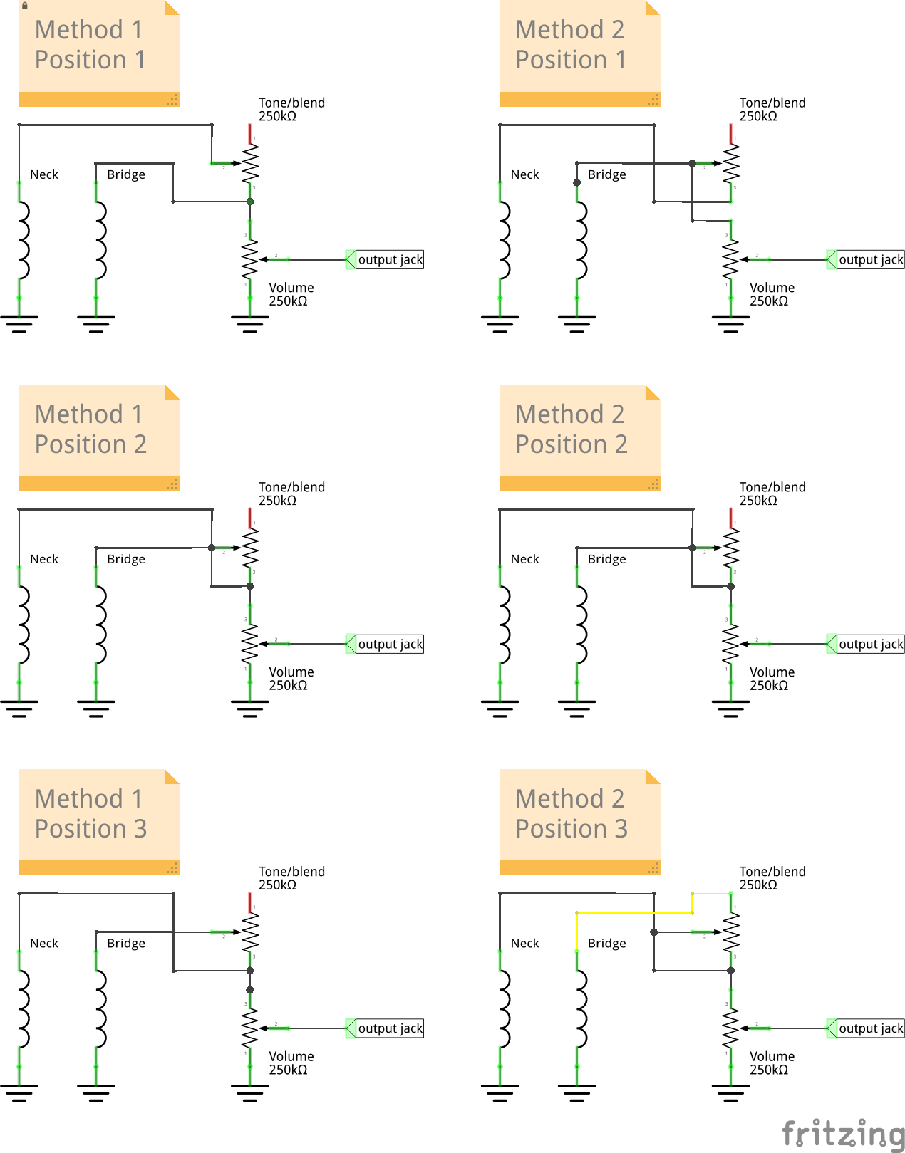
enter image description here

I followed the switch schematic from the video you linked:

         A1
            B1 - Neck
         A2
           B2
         A3
           B3
Bridge - A4
           B4
  • Position 1 connects A4-A1, and B2-B1
  • Position 2 connects A4-A2, and B3-B1
  • Position 3 connects A4-A3, and B4-B1

I was able to trace the signal flow in all three positions, for both diagrams in your post, i.e.

I believe the Method 1 is what you want:

  • Position 1 gives bridge pickup, with the tone pot allowing to add the neck pickup (in parallel).
  • Position 2 gives two pickups in parallel. The tone pot does nothing.
  • Position 3 gives neck pickup, with the tone pot allowing to add the bridge pickup in parallel.

Both in positions 1 and 3, the tone pot controls the amount of blend the same way, so in one extreme setting all 3 positions would sound the same, and in the other extreme setting there would be (almost) no blending.

Note, the tone pot in the diagram is logarithmic. Again, I can't remember which way the log pot turns, but depending on which pair of terminals on the pot you use (you need to use the middle, and one of the side ones), the blending will be more or less smooth.

Method 2 is similar, with one exception:

  • Position 3 gives only neck pickup. The tone pot does nothing.

You could add blending, by connecting the A3 terminal to the third (unconnected) terminal of the tone pot. This would make blending work in the opposite way for positions 1 and 3, i.e. pot setting for maximum blending in position 1 would correspond to no blending in position 3, and the other way round. You probably would prefer a linear pot rather than logarithmic.

Edit: Below I'm attaching diagrams of the electrical circuits, for both methods in all 3 position of the switches. Please note in Method 1 Position 3 and Method 2 Position 1 some of the paths cross without connection. In Method 2 Position 3 I also added in yellow possible extra connection that would allow blending.

enter image description here

I followed the switch schematic from the video you linked:

Position 1  Position 2  Position 3
 ,-A1          A1          A1
 |   B1-.        B1-.        B1-.
 | A2   |    ,-A2   |      A2   |
 |   B2-'    |   B2 |        B2 |
 | A3        | A3   |    ,-A3   |
 |   B3      |   B3-'    |   B3 |
 `-A4        `-A4        `-A4   |
     B4          B4          B4-'
  • Hot wire of neck pickup connected to B1, Bridge pickup to A4
  • Position 1 connects A4-A1, and B2-B1
  • Position 2 connects A4-A2, and B3-B1
  • Position 3 connects A4-A3, and B4-B1

I was able to trace the signal flow in all three positions, for both diagrams in your post, i.e.

I believe the Method 1 is what you want:

  • Position 1 gives bridge pickup, with the tone pot allowing to add the neck pickup (in parallel).
  • Position 2 gives two pickups in parallel. The tone pot does nothing.
  • Position 3 gives neck pickup, with the tone pot allowing to add the bridge pickup in parallel.

Both in positions 1 and 3, the tone pot controls the amount of blend the same way, so in one extreme setting all 3 positions would sound the same, and in the other extreme setting there would be (almost) no blending.

Note, the tone pot in the diagram is logarithmic. Again, I can't remember which way the log pot turns, but depending on which pair of terminals on the pot you use (you need to use the middle, and one of the side ones), the blending will be more or less smooth.

Method 2 is similar, with one exception:

  • Position 3 gives only neck pickup. The tone pot does nothing.

You could add blending, by connecting the A3 terminal to the third (unconnected) terminal of the tone pot. This would make blending work in the opposite way for positions 1 and 3, i.e. pot setting for maximum blending in position 1 would correspond to no blending in position 3, and the other way round. You probably would prefer a linear pot rather than logarithmic.

Edit: Below I'm attaching diagrams of the electrical circuits, for both methods in all 3 position of the switches. Please note in Method 1 Position 3 and Method 2 Position 1 some of the paths cross without connection. In Method 2 Position 3 I also added in yellow possible extra connection that would allow blending.

enter image description here

diagrams
Source Link
user1079505
  • 17.8k
  • 2
  • 28
  • 69

I followed the switch schematic from the video you linked:

         A1
           B1 - Neck
         A2
           B2
         A3
           B3
Bridge - A4
           B4
  • Position 1 connects A4-A1, and B2-B1
  • Position 2 connects A4-A2, and B3-B1
  • Position 3 connects A4-A3, and B4-B1

I was able to trace the signal flow in all three positions, for both diagrams in your post, i.e.

I believe the Method 1 is what you want:

  • Position 1 gives bridge pickup, with the tone pot allowing to add the neck pickup (in parallel).
  • Position 2 gives two pickups in parallel. The tone pot does nothing.
  • Position 3 gives neck pickup, with the tone pot allowing to add the bridge pickup in parallel.

Both in positions 1 and 3, the tone pot controls the amount of blend the same way, so in one extreme setting all 3 positions would sound the same, and in the other extreme setting there would be (almost) no blending.

Note, the tone pot in the diagram is logarithmic. Again, I can't remember which way the log pot turns, but depending on which pair of terminals on the pot you use (you need to use the middle, and one of the side ones), the blending will be more or less smooth.

Method 2 is similar, with one exception:

  • Position 3 gives only neck pickup. The tone pot does nothing.

You could add blending, by connecting the A3 terminal to the third (unconnected) terminal of the tone pot. This would make blending work in the opposite way for positions 1 and 3, i.e. pot setting for maximum blending in position 1 would correspond to no blending in position 3, and the other way round. You probably would prefer a linear pot rather than logarithmic.

I can add theEdit: Below I'm attaching diagrams if you wishof the electrical circuits, butfor both methods in all 3 position of the switches. Please note in Method 1 Position 3 and Method 2 Position 1 some of the paths cross without connection. In Method 2 Position 3 I also added in yellow possible extra connection that would need some time to draw them nicelyallow blending.

enter image description here

I followed the switch schematic from the video you linked:

         A1
           B1 - Neck
         A2
           B2
         A3
           B3
Bridge - A4
           B4
  • Position 1 connects A4-A1, and B2-B1
  • Position 2 connects A4-A2, and B3-B1
  • Position 3 connects A4-A3, and B4-B1

I was able to trace the signal flow in all three positions, for both diagrams in your post, i.e.

I believe the Method 1 is what you want:

  • Position 1 gives bridge pickup, with the tone pot allowing to add the neck pickup (in parallel).
  • Position 2 gives two pickups in parallel. The tone pot does nothing.
  • Position 3 gives neck pickup, with the tone pot allowing to add the bridge pickup in parallel.

Both in positions 1 and 3, the tone pot controls the amount of blend the same way, so in one extreme setting all 3 positions would sound the same, and in the other extreme setting there would be (almost) no blending.

Note, the tone pot in the diagram is logarithmic. Again, I can't remember which way the log pot turns, but depending on which pair of terminals on the pot you use (you need to use the middle, and one of the side ones), the blending will be more or less smooth.

Method 2 is similar, with one exception:

  • Position 3 gives only neck pickup. The tone pot does nothing.

You could add blending, by connecting the A3 terminal to the third (unconnected) terminal of the tone pot. This would make blending work in the opposite way for positions 1 and 3, i.e. pot setting for maximum blending in position 1 would correspond to no blending in position 3, and the other way round. You probably would prefer a linear pot rather than logarithmic.

I can add the diagrams if you wish, but I would need some time to draw them nicely.

I followed the switch schematic from the video you linked:

         A1
           B1 - Neck
         A2
           B2
         A3
           B3
Bridge - A4
           B4
  • Position 1 connects A4-A1, and B2-B1
  • Position 2 connects A4-A2, and B3-B1
  • Position 3 connects A4-A3, and B4-B1

I was able to trace the signal flow in all three positions, for both diagrams in your post, i.e.

I believe the Method 1 is what you want:

  • Position 1 gives bridge pickup, with the tone pot allowing to add the neck pickup (in parallel).
  • Position 2 gives two pickups in parallel. The tone pot does nothing.
  • Position 3 gives neck pickup, with the tone pot allowing to add the bridge pickup in parallel.

Both in positions 1 and 3, the tone pot controls the amount of blend the same way, so in one extreme setting all 3 positions would sound the same, and in the other extreme setting there would be (almost) no blending.

Note, the tone pot in the diagram is logarithmic. Again, I can't remember which way the log pot turns, but depending on which pair of terminals on the pot you use (you need to use the middle, and one of the side ones), the blending will be more or less smooth.

Method 2 is similar, with one exception:

  • Position 3 gives only neck pickup. The tone pot does nothing.

You could add blending, by connecting the A3 terminal to the third (unconnected) terminal of the tone pot. This would make blending work in the opposite way for positions 1 and 3, i.e. pot setting for maximum blending in position 1 would correspond to no blending in position 3, and the other way round. You probably would prefer a linear pot rather than logarithmic.

Edit: Below I'm attaching diagrams of the electrical circuits, for both methods in all 3 position of the switches. Please note in Method 1 Position 3 and Method 2 Position 1 some of the paths cross without connection. In Method 2 Position 3 I also added in yellow possible extra connection that would allow blending.

enter image description here

fix ASCII diagram
Source Link
user1079505
  • 17.8k
  • 2
  • 28
  • 69

I followed the switch schematic from the video you linked:

         A1
           B1 - Neck
         A2
           B2
         A3
           B3
Bridge - A4
           B4

         A1
           B1 - Neck
         A2
           B2
         A3
           B3
Bridge - A4
           B4
  • Position 1 connects A4-A1, and B2-B1
  • Position 2 connects A4-A2, and B3-B1
  • Position 3 connects A4-A3, and B4-B1

I was able to trace the signal flow in all three positions, for both diagrams in your post, i.e.

I believe the Method 1 is what you want:

  • Position 1 gives bridge pickup, with the tone pot allowing to add the neck pickup (in parallel).
  • Position 2 gives two pickups in parallel. The tone pot does nothing.
  • Position 3 gives neck pickup, with the tone pot allowing to add the bridge pickup in parallel.

Both in positions 1 and 3, the tone pot controls the amount of blend the same way, so in one extreme setting all 3 positions would sound the same, and in the other extreme setting there would be (almost) no blending.

Note, the tone pot in the diagram is logarithmic. Again, I can't remember which way the log pot turns, but depending on which pair of terminals on the pot you use (you need to use the middle, and one of the side ones), the blending will be more or less smooth.

Method 2 is similar, with one exception:

  • Position 3 gives only neck pickup. The tone pot does nothing.

You could add blending, by connecting the A3 terminal to the third (unconnected) terminal of the tone pot. This would make blending work in the opposite way for positions 1 and 3, i.e. pot setting for maximum blending in position 1 would correspond to no blending in position 3, and the other way round. You probably would prefer a linear pot rather than logarithmic.

I can add the diagrams if you wish, but I would need some time to draw them nicely.

I followed the switch schematic from the video you linked:

         A1
           B1 - Neck
         A2
           B2
         A3
           B3
Bridge - A4
           B4
  • Position 1 connects A4-A1, and B2-B1
  • Position 2 connects A4-A2, and B3-B1
  • Position 3 connects A4-A3, and B4-B1

I was able to trace the signal flow in all three positions, for both diagrams in your post, i.e.

I believe the Method 1 is what you want:

  • Position 1 gives bridge pickup, with the tone pot allowing to add the neck pickup (in parallel).
  • Position 2 gives two pickups in parallel. The tone pot does nothing.
  • Position 3 gives neck pickup, with the tone pot allowing to add the bridge pickup in parallel.

Both in positions 1 and 3, the tone pot controls the amount of blend the same way, so in one extreme setting all 3 positions would sound the same, and in the other extreme setting there would be (almost) no blending.

Note, the tone pot in the diagram is logarithmic. Again, I can't remember which way the log pot turns, but depending on which pair of terminals on the pot you use (you need to use the middle, and one of the side ones), the blending will be more or less smooth.

Method 2 is similar, with one exception:

  • Position 3 gives only neck pickup. The tone pot does nothing.

You could add blending, by connecting the A3 terminal to the third (unconnected) terminal of the tone pot. This would make blending work in the opposite way for positions 1 and 3, i.e. pot setting for maximum blending in position 1 would correspond to no blending in position 3, and the other way round. You probably would prefer a linear pot rather than logarithmic.

I can add the diagrams if you wish, but I would need some time to draw them nicely.

I followed the switch schematic from the video you linked:


         A1
           B1 - Neck
         A2
           B2
         A3
           B3
Bridge - A4
           B4
  • Position 1 connects A4-A1, and B2-B1
  • Position 2 connects A4-A2, and B3-B1
  • Position 3 connects A4-A3, and B4-B1

I was able to trace the signal flow in all three positions, for both diagrams in your post, i.e.

I believe the Method 1 is what you want:

  • Position 1 gives bridge pickup, with the tone pot allowing to add the neck pickup (in parallel).
  • Position 2 gives two pickups in parallel. The tone pot does nothing.
  • Position 3 gives neck pickup, with the tone pot allowing to add the bridge pickup in parallel.

Both in positions 1 and 3, the tone pot controls the amount of blend the same way, so in one extreme setting all 3 positions would sound the same, and in the other extreme setting there would be (almost) no blending.

Note, the tone pot in the diagram is logarithmic. Again, I can't remember which way the log pot turns, but depending on which pair of terminals on the pot you use (you need to use the middle, and one of the side ones), the blending will be more or less smooth.

Method 2 is similar, with one exception:

  • Position 3 gives only neck pickup. The tone pot does nothing.

You could add blending, by connecting the A3 terminal to the third (unconnected) terminal of the tone pot. This would make blending work in the opposite way for positions 1 and 3, i.e. pot setting for maximum blending in position 1 would correspond to no blending in position 3, and the other way round. You probably would prefer a linear pot rather than logarithmic.

I can add the diagrams if you wish, but I would need some time to draw them nicely.

added 318 characters in body
Source Link
user1079505
  • 17.8k
  • 2
  • 28
  • 69
Loading
Source Link
user1079505
  • 17.8k
  • 2
  • 28
  • 69
Loading