3

In Serum, it is possible to do something like (with many variations) drag an LFO onto an OSC parameters, and also drag that same LFO onto its own RATE parameter. This tends to result in a sound which is wild, but not entirely arbitrary, having some vaguely discernible patterns of periodicity when listed to for a while.

In principle, doing this might be expected to cause an infinite loop, with the LFO stuck referring to both its own envelope and its own RATE in order to compute its own RATE. What is actually happening here? How many iterations of self-reference does Serum execute? What value does it feed into the "earliest" iteration (a.k.a., the most abstract iteration; a.k.a., the most distant iteration from the one which actually modifies the sound wave)? Is there an intuitive way to think about how (or even a precise formula to put into graphic software) to modify a sound wave up to a certain number of such iterations?

1
  • The output of an LFO is a value that doesn’t mean anything until it is connected with an input, so you don’t have to worry about rate affecting rate, because that’s not possible. The LFO value would affect rate if that’s what you map it to. As the value goes high the rate of the LFO goes up which just makes the LFO go lower in a shorter amount of time. This would result in an LFO having an asymmetrical waveform but not a problematic feedback loop. Commented Aug 27 at 22:13

2 Answers 2

5

I don't have Serum, but I guess the answer is similar for any synthesizer.

Mathematically, LFO can be described as a function of internal phase of the oscillator LFO = func(phi) where func represents the oscillator function, e.g. sine, square, triangle, sawtooth, etc.

The phase increases in time at a given rate: phi(t) = integral from 0 to t over 2π r(t)dt where r is the rate.

With LFO modulating its own rate, the rate can be expressed as:

r(t) = r0 + m·LFO(phi(t)) where r₀ is the base rate setting on the LFO, and m is the modulation depth, or more likely as: r(t) = r0 * exp(m·LFO(phi(t))) as to me exponential modulation seems more logical for this parameter. The whole equation for LFO then becomes: LFO=func(integral(r0·exp[m·LFO(phi(t))]dt) So indeed there is a self-reference of LFO in the equation, which might be confusing. Mathematicians don't solve this type of equations by calling the function over and over, but rather by smartly guessing a function (in this case: LFO(t)) which would solve the equation. If you want to learn more mathoverflow is probably a good site.

A digital synthesizer solves this equation numerically, with an algorithm that could be schematically presented as:

for each time step:
    phase += rate * dt
    lfo_output = func(phase % 360°)
    rate = rate_setting * exp( modulation_depth * lfo_output )

Note, this is not a state of the art algorithm to solve numerical equations, but rather a simple way to present the idea. In particular, I made two approximations:

  • the present value of LFO output is approximated by the value from the previous time step
  • the LFO output is assumed to be constant between the time steps.

No such approximations were present in the analytical formula (Eq. 5). See e.g. Urs Heckmann article on Zero Delay Feedback about attempts to minimize the error introduced by the numerical algorithms.

Nevertheless, the value of LFO at a given time is calculated based on the value(s?) from the previous time steps, so in a way there is very deep recursion.

While finding the functional representation of the output might be difficult, I can provide some intuition:

  1. the function will be periodic
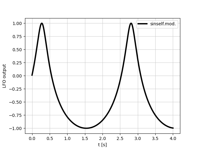
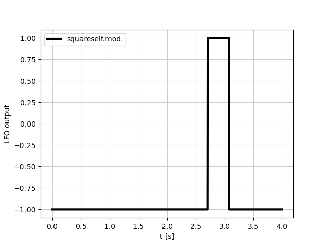
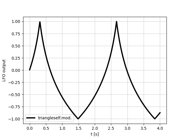
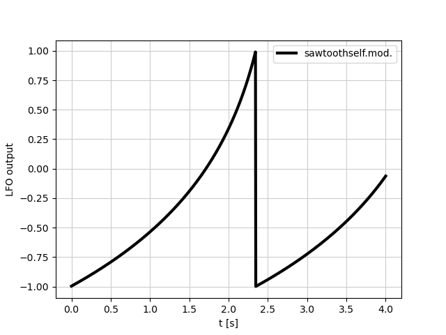
  2. the lower parts of the LFO function will become wider and the upper ones thinner (or the other way round for negative modulation)
  3. for symmetric initial LFO shape and bipolar modulation, the effective rate will decrease, because stretching the lower parts by some factor, and squeezing the top parts by the same factor results in overall stretching of the waveform

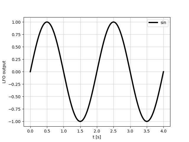
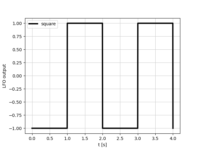
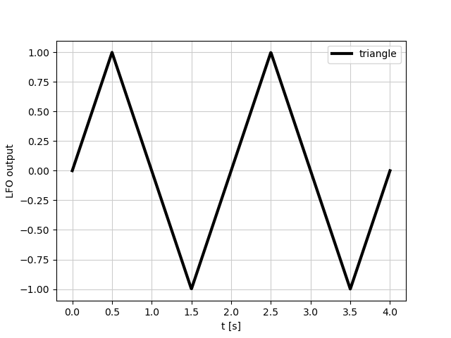
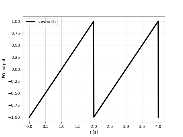
Below I present the effect on several common oscillator shapes. In all cases, base rate r₀ = 0.5 Hz (period 2s) and modulation depth m = 1, with exponential modulation (Eqs. 4 and 5). Notice how the upper and lower parts of the waveform are deformed differently, and how the effective rate changes differently depending on the waveform shape (in particular compare square wave with the others). sine wave sine wave self modulated square wave square wave self modulated triangle wave triangle wave self modulated sawtooth wave sawtooth wave self modulated

Similar idea is used in self-modulation in FM synthesis. See this video, where the author demonstrates how the shape of the function changes with self-modulation:

Note, there is no infinite loop and nothing blows up. Similar phenomena can be found in nature. Perhaps the following analogy may help: think of a planet orbiting a sun on an elliptical orbit. When the distance (analogue of LFO output) between the planet and the sun decreases, the gravitational pull increases, so the planet velocity (analogue of rate) increases. As the planet moves faster, the distance to the sun decreases even faster etc.

4
  • 1
    I think the relevant point the OP needs to realize is that there's a delay of 1 sample between the output of the LFO affecting the input. At each step, the LFO's rate value it uses to proceed, "phase += rate * dt", comes from the output the LFO had in the previous sample i.e. at time "t - 1". The feedback is not as instantaneous as it would be in real analog life, and particularly, it doesn't require analytically solving the whole signal path. The signal path is run sample-by-sample, and feedback loops have a delay. I suppose this is how it works in most modules+connections systems. Commented Aug 28 at 18:27
  • Natural phenomena do not have a 1-sample delay in cause-and-effect interactions, even in feedback loops. If we don't consider a DSP system a natural phenomenon, that is. :) Commented Aug 28 at 18:40
  • @piiperiReinstateMonica the algorithm I present is schematic and likely doesn't represent all details of the actual instrument, e.g. approaches to minimize aliasing and optimize performance. In particular, I don't know if the step dt in Serum is 1 sample or maybe 2 or half sample. However, I'm not sure if the delay is as relevant in this question as you present it. In a perfect mathematical world with no delays, you could construct such self modulated oscillator. It would work just fine, and the output wouldn't differ much from the digital simulation, at least within some range of parameters. Commented Aug 28 at 22:45
  • The OP thought that the process() functions of nodes invoke the process() functions of their input nodes, which would have meant infinite recursion in case of a feedback loop routing. Commented Aug 30 at 16:19
3

In principle, doing this might be expected to cause an infinite loop, with the LFO stuck referring to both its own envelope and its own RATE in order to compute its own RATE. What is actually happening here? How many iterations of self-reference does Serum execute? What value does it feed into the "earliest" iteration (a.k.a., the most abstract iteration; a.k.a., the most distant iteration from the one which actually modifies the sound wave)?

Let me paraphrase how I think you think it works.

Let's say the LFO module is a function f(R,T) meaning the LFO's output at time T, with rate R. And because of the feedback loop, rate R is the LFO's output, you assume that this must mean an infinite recursion where the LFO's output would have to be calculated as f(f(f(f(f(f(...),T),T),T),T),T). But that's not how its done in actual systems.

I don't have Serum, and I think relatively few people on this site have it either. Even fewer have Serum's source code. I most certainly don't. But I'm fairly sure that Serum doesn't process its output like that. Modular DSP systems where you can connect the inputs and outputs of signal-processing components or "nodes" (such as oscillator, envelope generator, filter, gain, delay) are programmed so that for each sample - or a whole buffer worth of samples - the signal path is processed in some order, once per node for each sample (or batch of samples).

As pseudo code, the processing logic is very simple:

for each node: node.process()

Nodes do not call other nodes. There is no recursion, regardless of how inputs and outputs are routed.

Each node's "process()" function produces one output value (or a batch of values if processing is done in "buffers" to reduce overhead) for each of its outputs (it may have several distinct outputs). An output value is a number that can be stored in a variable inside the node instance's memory. The process() function performs its calculations by using its inputs, which are also numbers. The numbers come from whatever is routed to the inputs in the signal path. You can think of signal routing arrows as pointers or references to variables. An input routing is a pointer to a number variable somewhere in memory. (The pointer points backwards compared to what you'd draw in a arrow drawing.)

The signal path is a directed graph, and a good processing order is to run the process() functions in decreasing root distance in the graph. The system's master outputs are the "root" node of the graph. The first nodes to be processed are ones that are the furthest from the root.

Here's an example routing with an External Audio Input, an LFO, a Filter and a Master Audio Output node. And the LFO's output is routed to its own Rate input.
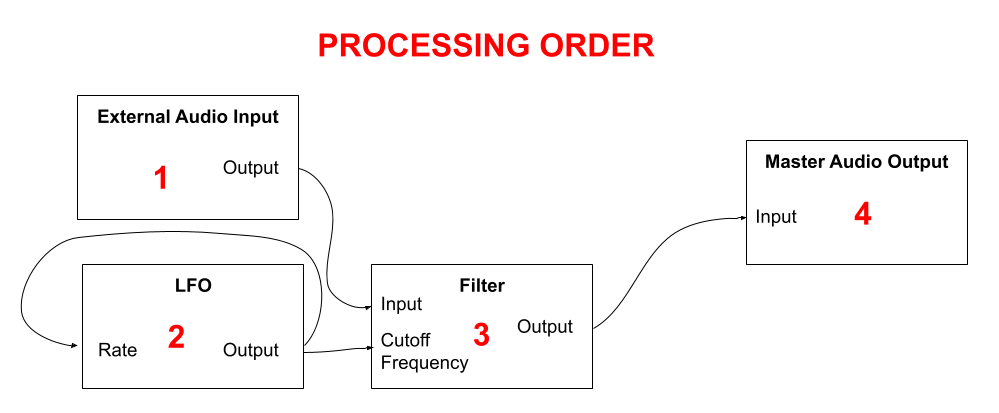
example signal path graph

The root distance order places these nodes in an order where

  • (Root distance 2) the External Audio Input and the LFO are process()'ed first, in any order or even simultaneously in parallel, but let's say they're 1 and 2 like in the picture,
  • (Root distance 1) the Filter node is done next,
  • (Root distance 0) and finally the Master Audio Output.

What to do with cycles in the graph? You have to resolve cycles somehow and determine that there's a feedback loop from the LFO's output to its Rate input, and you ignore that in the root distance calculation.

What happens in the LFO module's process() function? What is given into its Rate input, since its source hasn't been calculated yet? Infinite recursion? No. The previous value of the Output is read into the Rate input, meaning that it gets whatever was calculated for the previous sample. In essence, there is a delay of one sample (or more if processing is done in larger than 1-sample buffers) in the feedback loop. When the LFO.process() function has done its thing, the result is stored in a variable, overwriting the number there was previously.

For parts of the signal path which don't have feedback loops or cycles in the graph, there is no delay. The Master Audio Output for sample of time T results directly from a Filter'ed External Audio Input of time T. (Ignoring that the Filter itself might have some delay in it.)

Is there an intuitive way to think about how (or even a precise formula to put into graphic software) to modify a sound wave up to a certain number of such iterations?

By "iteration" you mean recursion, but there's no actual recursion between processing functions, as I explained above. The process() functions of node objects do not call the process() functions of their input or output target nodes, and they don't call themselves either. Maybe if a node is a sub-module container for other nodes, then its process() function can call its children.

Caveat emptor: anyone with access to Serum's source code is welcome to post a more educated answer.

Your Answer

By clicking “Post Your Answer”, you agree to our terms of service and acknowledge you have read our privacy policy.

Not the answer you're looking for? Browse other questions tagged or ask your own question.